


-
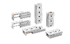
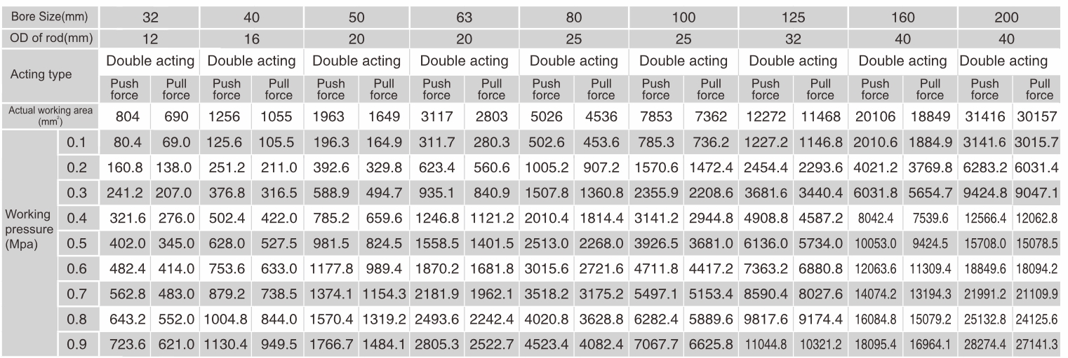
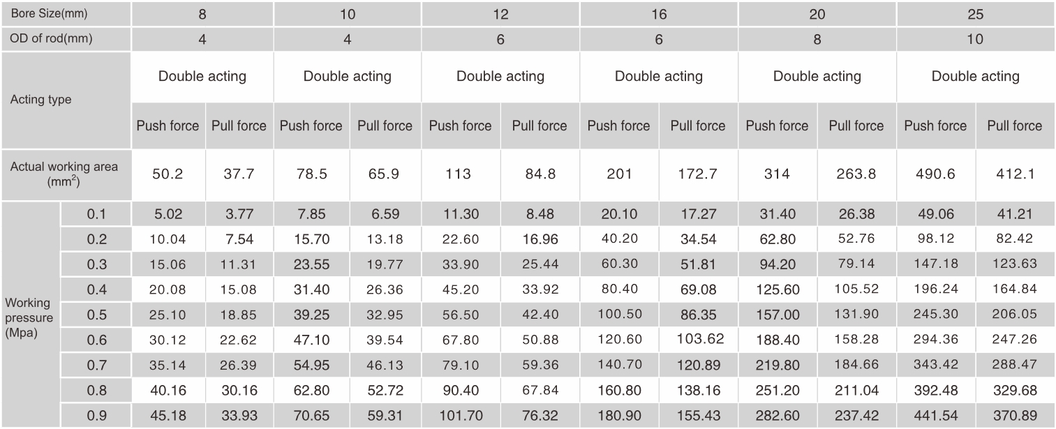
Air Cylinder Theory(Repeat Action Type) – Force Table
Air Cylinder Theory – Force Table
-
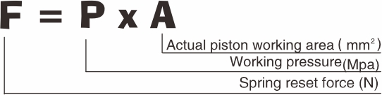
Theoretical cylinder force calculation method (single-acting type)

Air Cylinder Theory – Force Table
-
Installation and Use
1、 Prevent debris and dirt and other impurities into the cylinderbefore connect with pipe.1~1.5 thread pitch should be
reserved for wrapping tape. Don't wrap the tape around .
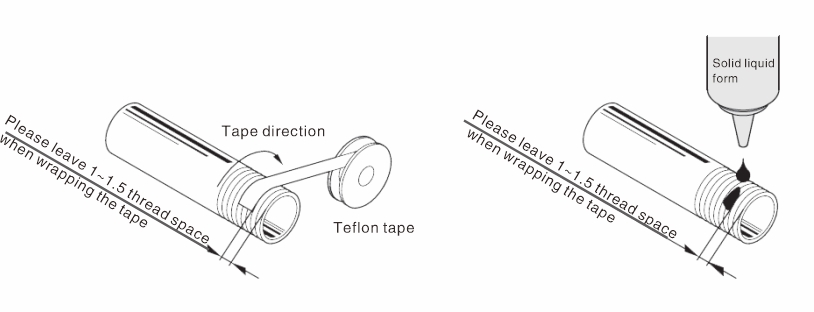
2、To avoid overusing or inflowing of the liquid glue into the body when using liquid fixing glue (anaerobic adhesive) to lock the fitting, or it will get the parts stuck, leading not good performance.
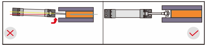
3、The axes of piston rod shall corresponde with the moving direction of load (coaxial). Piston rod and cylinder will produce opposite force which can easily damage the internal,The internal surface of the cylinder, guide sleeve, the surface of piston rod and seals.
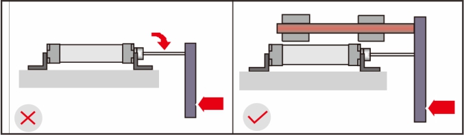
4、Avoid direct connection of piston rod, or it will suffer vertical gravity: it shall add idler wheels under the load bottom to support the guide rail(as in below right photo).It is wrong installation as in below left photo, because the piston rod and cylinder will produce opposite force which can easily bend piston rod and damage the internal surface of the cylinder, guide sleeve, the surface of piston rod and seals.
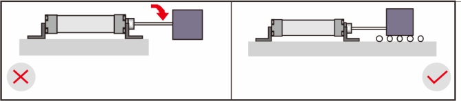
5、Avoid direct connection of piston rod, or it will suffer vertical gravity: it shall add idler wheels under the load bottom to support the guide rail(as in below right photo).It is wrong installation as in below left photo,because the piston rod and cylinder will produce opposite force which can easily bend piston rod and damage the internal surface of the cylinder, guide sleeve, the surface of piston rod and seals.
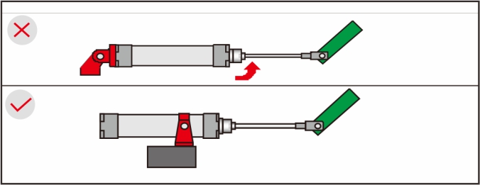
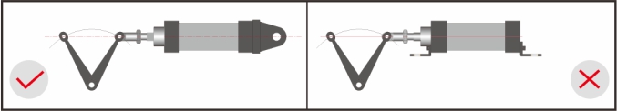
6、To prevent that back activity hinge is far from force supply point, the piston rod will be influenced by torque force. To use middle action support to shorten the long distance between support point and force supply point.
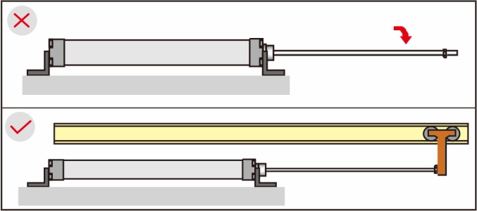
7、Long-stroke cylinder shall set middle guide support to prevent natural drop of piston rod and to prevent the damage on piston rod caused by the droop of piston rod, bend of the cylinder, vibration and external load.
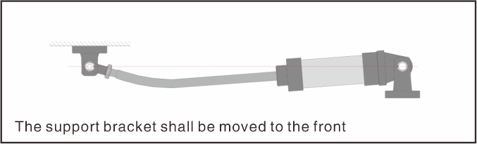
8、It tends to bend at long stroke, thus the installation bracket shall be moved to the front cover.
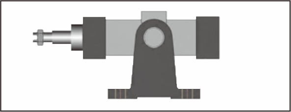
9、The fixed cylinder shall not be connected with the rocker carrying out circular action (fixed with LB). At this time, it shall be connected with swing cylinder (fixed with CA/ CB/TC )
10、If the height (H) between installation surface of bearing bracket and the position of bearing is too great, when cylinder works, the installation part of the support will produce great torque force,Which may cause damage to installing bolt and other parts.
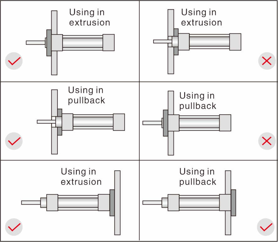
11、Proper installation shall be adopted considering the directionof load (flange type installation).
Customized Products, Better Solution
With "Eternal innovation and faithful working", from good to great, we strives to offer more value to all our customers and partners.


